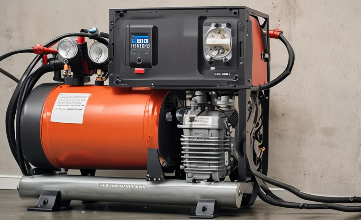
Air compressors are essential tools used in a variety of industries, from construction to automotive. These powerful machines are responsible for converting electrical energy into kinetic energy, which is then used to power pneumatic tools and equipment.
However, for an air compressor to function properly, it needs to be wired correctly. This is where a wiring diagram comes into play. A wiring diagram is a visual representation of the electrical connections and components of a system.
Here, we will discuss the air compressor wiring diagram 240v compressor, outlining the necessary components and connections needed for its installation. We will also provide a step-by-step guide on how to wire a 240v air compressor correctly, along with important safety precautions to keep in mind.
Basic Tools And Materials Required For Wiring
The tools and materials required may vary depending on the air compressor model and wiring diagram. It is important to refer to the manufacturer’s instructions and consult a qualified electrician if unsure about any aspect of the wiring process. Here are the Basic Tools and Materials Required for Wiring:
Tools:
- Screwdrivers (flathead and Phillips)
- Wire strippers
- Wire cutters
- Pliers (needle-nose and adjustable)
- Electrical tape
- Voltage tester
- Wire connectors (such as wire nuts or crimp connectors)
- Multimeter
- Drill and drill bits (if needed for mounting)
- Safety goggles
- Insulated gloves
- Wire labels or markers
Materials:
- Air compressor
- 240V power supply
- A circuit breaker or fuse box
- Electrical wires (an appropriate gauge for the compressor’s power requirements)
- Junction boxes or electrical enclosures (if needed)
- Mounting brackets or straps (if needed)
- Conduit or cable channels (if needed for wire protection)
- Wire nuts or crimp connectors (appropriate size for wire gauge)
- Wire staples or clips (if needed for securing wires)
- Grounding wire and grounding clamp
- Terminal block (if needed for connecting multiple wires)
Step-By-Step Instructions For Air Compressor Wiring Diagram 240v
An air compressor wiring diagram for a 240v circuit typically includes information on where to connect the incoming power wires, the grounding wire, and the separate wire that connects to the motor.
It may also show any necessary circuit protection devices, such as fuses or circuit breakers. Following the diagram carefully can help ensure the safe and proper installation of the compressor. Here are some tips on air compressor wiring diagram 240v.
1.Identify Power Source And Voltage
The first step in wiring an air compressor is identifying the power source and voltage. The power source can be a dedicated circuit from the main panel or a subpanel. The voltage can be either 120V or 240V, depending on the compressor model and the wiring configuration. You can determine the voltage by checking the compressor’s nameplate or manual or using a multimeter to measure the voltage at the power source.
2.Select The Suitable Wiring Method
The next step is selecting a suitable air compressor wiring method. The wiring method should comply with the local electrical codes and the manufacturer’s instructions. The wiring method should also match the voltage and amperage of the compressor, as well as the distance and location of the installation.
Some common wiring methods are NM cable, UF cable, conduit, and armoured cable. The wiring method should include a disconnect switch, a circuit amp breaker, and a grounding wire.
3.Install And Mount Disconnect Switch
The third step is to install and mount a disconnect switch for the air compressor. The disconnect switch allows you to turn off the power to the compressor when it is not in use or when you are servicing it.
The disconnect switch should be located near the compressor, within sight and reach, and clearly labelled. However, the disconnect switch should be rated at least 240V and have the same amperage as the compressor. You should securely mount the disconnect switch to a wall or a box using screws or bolts.
4.Run Power Supply Cable
The fourth step is to run the power supply cable from the power source to the disconnect switch. The power supply cable should be sized according to the voltage and amperage of the compressor, as well as the length and type of the cable.
For example, a 240V, 15-amp compressor may require a 14-gauge NM cable for up to 50 feet or a 12-gauge NM cable for up to 100 feet. The power supply cable should be routed along walls, ceilings, or floors, using staples, clamps, or straps to secure it. The power supply cable should also have enough slack to allow for movement and vibration of the compressor.
5.Connect The Wiring To The Compressor Motor
The fifth step is to connect the wiring to the compressor motor. The compressor motor should have a terminal box or a junction box with wires or terminals labeled for line, neutral, and ground wire. The wiring should follow the color code of black wire for line, white for neutral, and green or bare for ground.
The wiring should also match the polarity of the power source, with line connected to line, neutral connected to neutral, and ground connected to ground. However, the wiring should be secured with wire nuts or crimp connectors and tucked inside the terminal or junction box.
6.Secure And Insulate Connections
The sixth step is to secure and insulate all the connections for the air compressor wiring. The connections should be checked for tightness and continuity using a screwdriver and a multimeter. Electrical tape or heat-shrink tubing should also cover the connections to prevent short circuits or shocks. The connections should also be protected from moisture, dust, dirt, or damage using conduit fittings, junction boxes, or wire loom.
7.Grounding The Air Compressor
The seventh step is to ground the air compressor properly. Grounding is essential for the safety and performance of the air compressor. Grounding provides a path for excess current to flow in case of a fault or overload, preventing fires or shocks.
However, grounding also reduces electrical noise and interference that may affect the operation of the compressor. However, grounding can be done by connecting a grounding wire from the compressor motor to a grounding rod, a metal water pipe, or a conduit.
8.Test And Verify Wiring
The final step is to test and verify the wiring for the air compressor. Before turning on the power, ensure all the switches are off, all the covers are in place, and all the tools remove. Then, turn on the power at the main panel or subpanel and check for sparks, smoke, or tripped breakers.
If everything is normal, turn on the disconnect switch and check for any abnormal sounds or vibrations from the compressor. However, if everything is normal, turn on the pressure switch and check for any leaks or malfunctions from the pressure gauge, relief valve, drain valve, or hose fittings. If everything is normal, congratulations! You have successfully wired your air compressor.
Tips For Troubleshooting Common Wiring Issues
One cannot underestimate the importance of a reliable and efficient air compressor. An air compressor is a device that converts power, usually from an electrical motor or a diesel engine, into potential energy stored in compressed air.
This compressed air can then be handy in a variety of applications, such as powering pneumatic tools, manufacturing processes, and even operating HVAC systems. Here are Tips For Troubleshooting Common Wiring Issues.
- Check The Power Source: Ensure that the air compressor properly connect to a functioning power outlet. Confirm that the circuit breaker or fuse not trip or blow.
- Inspect The Power Cord: Look for any visible damage or frayed wires on the power cord. If there are any issues, replace the cord with a new one.
- Test The On/Off Switch: Verify that the on/off switch is in the correct position and functioning properly. If necessary, replace the switch.
- Examine The Pressure Switch: Make sure the pressure switch is set to the correct pressure setting and is not faulty. Adjust or replace the switch if needed.
- Check For Air Leaks: Inspect the air hoses, fittings, and connections for any leaks. Use soapy water to identify leaks by applying it to the suspected areas and looking for bubbles. Repair or replace any damaged components.
- Inspect The Motor: Look for any signs of overheating or burning smells coming from the motor. If there are any issues, consult a professional for motor repair or replacement.
- Test The Capacitor: If the motor is not starting, check the capacitor for any signs of damage or failure. Replace the capacitor if necessary.
Safety Precautions When Working With Electricity
Air compressors are an important piece of equipment in various industries, making them a crucial tool for businesses across the globe. These powerful machines have specific designs to convert power into potential energy stored in pressurized air.
They play a vital role in powering pneumatic tools, supplying clean air for various processes, and maintaining consistent pressure in production lines. When working with an air compressor, it is important to follow safety precautions when dealing with electricity. Here are some guidelines to ensure your safety:
- Disconnect The Power: Before performing any maintenance or repairs on the air compressor, make sure to turn off the power supply and unplug the unit. This will prevent accidental electric shocks or injuries.
- Inspect Power Cords: Regularly check the power cords for any signs of damage or wear. If you notice any frayed wires or exposed insulation, replace the cord immediately to avoid electrical hazards.
- Grounding: Ensure that the air compressor is properly grounded to prevent electric shocks. Follow the manufacturer’s instructions for grounding the equipment correctly.
- Use A GFCI: When using electrical equipment near water sources, such as when cleaning the air compressor, always plug it into a Ground Fault Circuit Interrupter (GFCI) outlet. A GFCI will shut off the power if it detects a ground fault, protecting you from electric shock.
- Avoid Wet Conditions: Never operate the air compressor in wet environments unless it is specifically designed for such conditions. Moisture can increase the risk of electrical shock.
- Use Proper Extension Cords: If you need to use an extension cord, ensure that it is the appropriate gauge and length for the power requirements of the air compressor. Using an inadequate or damaged extension cord can lead to overheating and electrical hazards.
Conclusion
Understanding the air compressor wiring diagram 240v is essential for safe and efficient operation. Understanding the wiring diagram for a 240v air compressor is crucial for safe and efficient operation.
By following the proper wiring instructions and precautions, you can ensure the longevity of your compressor and avoid any potential hazards. We hope this guide has provided you with the necessary information and that you feel confident in handling the wiring process.
Remember always to consult a professional electrician if you are unsure about any electrical work. With the correct wiring, your 240v air compressor will continue to provide reliable and powerful performance for all your pneumatic needs.
FAQ’s
[rank_math_rich_snippet id=”s-e8b90173-271c-41c5-b526-7c40600b4643″]
