Pressure switch wiring diagram air compressor is essential to any air compressor system. It controls the pressure level within the compressor and ensures that it operates within safe limits.
The pressure switch wiring diagram is a device that is designed to automatically turn on and turn off the compressor motor based on the pressure level in the tank. This is done to prevent any damage caused by over-pressurization or under-pressurization of the system.
The pressure switch wiring diagram is a crucial part of the air compressor system as it ensures that the compressor runs efficiently and effectively. Without this device, the compressor may run continuously, leading to overheating and damage to the motor. Therefore, it is important to ensure the pressure switch wiring diagram is properly installed and maintained to ensure the air compressor system runs smoothly.
Types Of Pressure Switches For Air Compressors
Pressure switches for air compressors are essential components that monitor the pressure levels within the compressor system and help regulate its operation. They are responsible for turning the compressor on and off based on pre-set pressure thresholds. There are several types of pressure switches commonly used for air compressors:
- Adjustable Differential Pressure Switches: These allow you to adjust both the cut-in (lower) and cut-out (upper) pressure settings. The differential is the difference between the two pressure levels at which the switch turns the compressor on and off.
- Fixed Differential Pressure Switches: Unlike adjustable switches, fixed differential switches have a pre-set differential, meaning you can only adjust the cut-in pressure. The cut-out pressure is fixed at a certain value above the cut-in pressure.
- Diaphragm Pressure Switches: Diaphragm switches use a flexible diaphragm that deforms under pressure changes, activating the switch to open or close the circuit. Air compressors commonly use these.
- Piston Pressure Switches: Piston switches use a piston mechanism to sense pressure changes and actuate the switch accordingly. Their reliability and durability were popular.
- Solid-State Pressure Switches: These switches do not use mechanical components like diaphragms or pistons. Instead, they employ electronic sensors to detect pressure changes and trigger the switch electronically.
Tools Required For Wiring A Pressure Switch
Wiring a pressure switch typically involves connecting the switch to an electrical circuit to control the operation of the air compressor or other devices based on pressure levels. To wire a pressure switch properly, you’ll need the following tools:
- Screwdrivers: You will need Phillips and flathead screwdrivers to loosen and tighten the terminal screws on the pressure switch and the electrical box.
- Wire Strippers: Wire strippers are handy for removing the insulation from the ends of the wires to expose the conductive copper.
- Wire Nuts: People use wire nuts to securely connect and protect the exposed ends of wires when making electrical connections.
- Electrical Tape: Electrical tape can further insulate wire connections and provide additional protection.
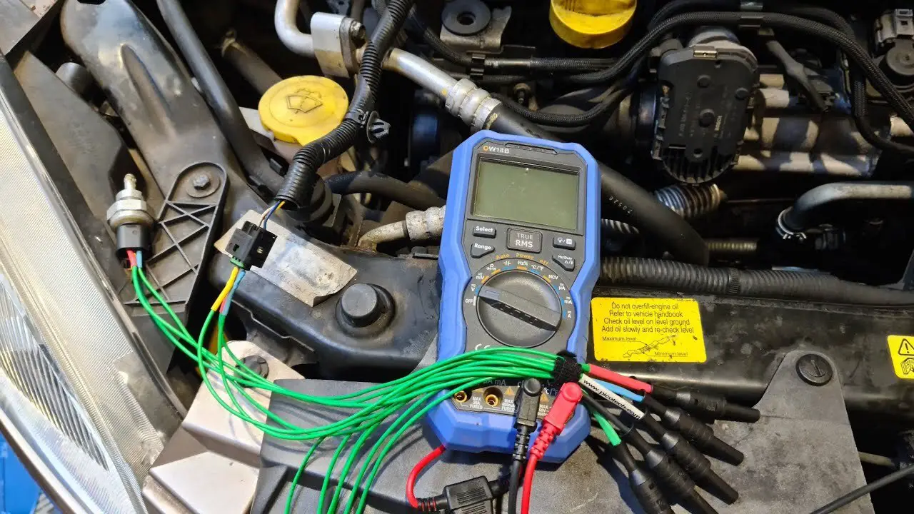
- Multimeter: A multimeter is an essential tool for testing the continuity of wires and ensuring proper voltage levels.
- Crimping Tool: If your pressure switch uses a spade or other crimp-style connectors, you’ll need a crimping tool to make secure connections.
- Electrical Box: Sometimes, you may need an electrical box to house the pressure switch and other electrical components.
- Wires: Depending on the specific installation, you may need additional wires to properly connect the pressure switch to the electrical circuit.
- Cable Clamps: Cable clamps are handy to secure and organize the wires to prevent them from being pinched or damaged.
- Drill and Bits: If you need to create holes for mounting the pressure switch or electrical box, a drill with appropriate drill bits will be necessary.
How To Pressure Switch Wiring Diagram Air Compressor
A pressure switch wiring diagram for an air compressor is essential in ensuring the machine’s safe and efficient operation. It visually represents the electrical connections between the power source, motor, and pressure switch. This diagram is critical in helping to troubleshoot any electrical issues that may arise during operation. Wiring an air compressor incorrectly can damage the machine, cause electrical shock, or even a fire hazard.
Therefore, following the manufacturer’s instructions and wiring diagram carefully is crucial when installing or repairing an air compressor. A pressure switch wiring diagram ensures proper electrical connections and safe operation of the machine. Here is explained Pressure switch wiring diagram air compressor.
Locate The Pressure Switch And Existing Wiring
When wiring an air compressor’s pressure switch, the first step is to locate the existing pressure switch and its wiring. The pressure switch usually sits near the compressor tank and regulates the compressor’s operation based on the air pressure. Once you find the pressure switch, carefully disconnect the existing wiring while ensuring that the power to the compressor is turned off to avoid accidents. Note how to connect the wires; installing the new pressure switch will require this information.
Disconnecting The Existing Wiring
Before installing a new pressure switch on your air compressor, it is crucial to disconnect the existing wiring properly. This ensures a safe and smooth transition to the new switch. Start by turning off the power to the compressor to eliminate any potential electrical hazards.
Next, carefully detach the wires from the old pressure switch. Take note of the wire colours and their corresponding terminals on the switch for reference during the installation process. Labelling the wires with tape can be helpful. Properly disconnecting the existing wiring sets the stage for a successful and trouble-free procedure.
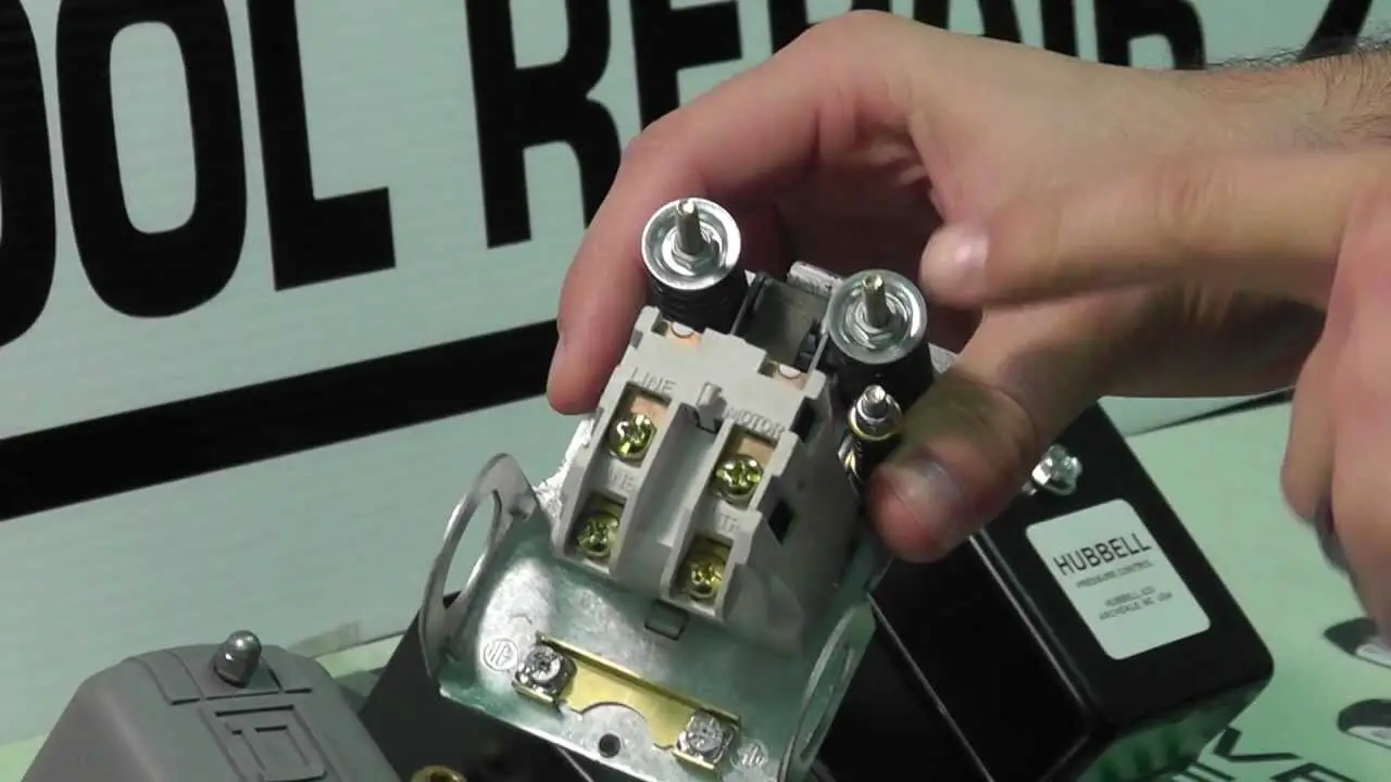
Identifying The Wires On The New Pressure Switch
When installing a new pressure switch on your air compressor, understanding the components of the new switch is essential. The pressure switch has a wiring diagram and specific terminals that serve distinct purposes. Take the time to review the manufacturer’s instructions and study the wiring diagram provided.
Identify the different terminals, such as those for the power supply and motor connections. Being familiar with the new pressure switch’s layout and functions will simplify the wiring process and help avoid potential errors that could lead to compressor malfunctions.
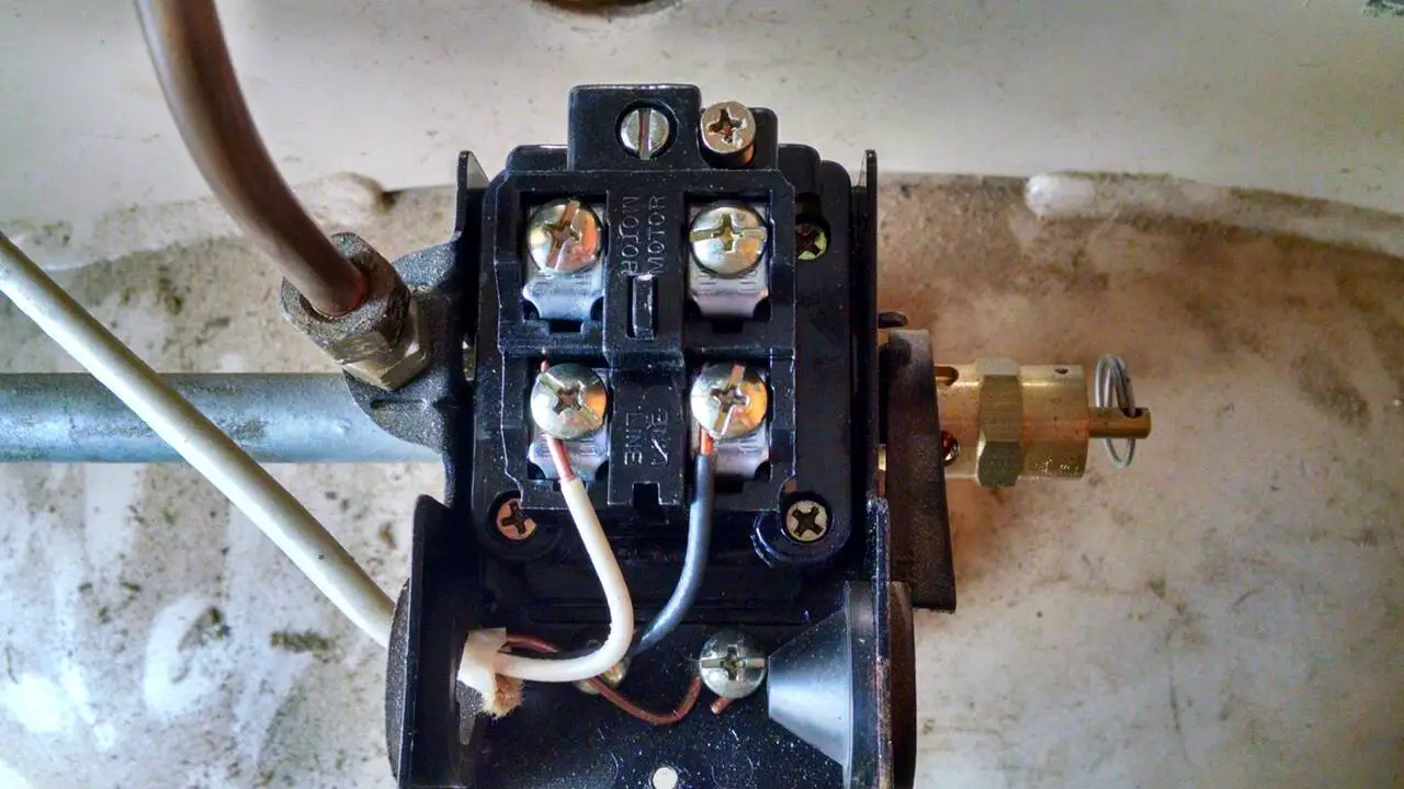
Connecting The Power Wires To The Pressure Switch
Wiring an air compressor’s pressure switch requires connecting the power supply wires to the appropriate terminals on the new switch. Typically, there are two power supply wires – one from the electrical panel and the other leading to the motor starter.
It’s crucial to make secure connections to ensure proper electrical flow and prevent loose connections that could lead to safety hazards or malfunctioning of the compressor. Following the manufacturer’s instructions and the wiring diagram will guide you in making accurate and safe connections for the power supply.
Connecting The Motor Wires To The Pressure Switch
After connecting the power supply wires, the next step in wiring an air compressor’s pressure switch is to attach the motor wires. The motor wires are responsible for powering the compressor motor. Carefully connect these wires to their designated terminals on the pressure switch.
Double-check that the connections are secure and free from any defects. Loose or improper connections may lead to erratic compressor performance or electrical problems. Ensuring proper attachment of the motor wires is crucial for the efficient and safe operation of the air compressor.
Adjusting The Pressure Switch Settings
Adjusting the pressure settings is essential to optimize the performance of an air compressor and the pressure switch. The pressure switch determines when the compressor starts and stops based on the air pressure in the tank. Most pressure switches come with adjustable cut-in and cut-out pressure settings.
Carefully follow the manufacturer’s guidelines to set the desired pressure levels. Ensure the cut-in pressure is lower than the cut-out pressure to prevent the compressor from starting and stopping rapidly. Properly adjusted pressure switch settings contribute to the compressor’s efficiency and longevity.
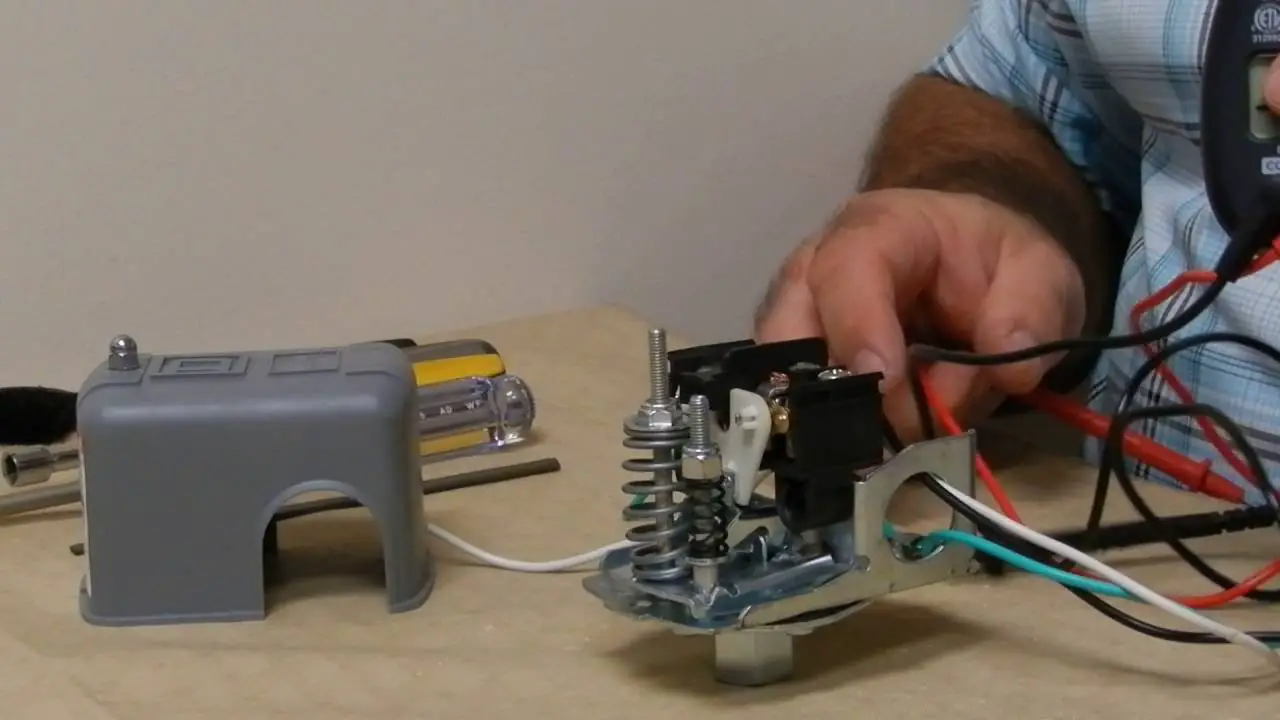
Testing The Pressure Switch And Compressor
Once the wiring is complete and the pressure switch settings are adjusted, testing the pressure switch and the air compressor is crucial. Turn on the power supply and observe the compressor’s behaviour. The pressure switch should activate the compressor when the tank pressure drops below the cut-in pressure and stop it when the pressure reaches the cut-out level.
Listen for unusual sounds or vibrations during the test, which may indicate potential issues. If everything functions as expected, you can proceed confidently, knowing that the pressure switch and compressor are working correctly.
Troubleshooting Common Wiring Issues With Pressure Switches
Despite careful installation, issues with pressure switch wiring may occasionally arise. To address common problems, consult the troubleshooting section in the pressure switch manual. Some typical issues include incorrect wiring, loose connections, or improperly adjusted pressure settings.
Ensure you check for loose or disconnected wires and securely connect them to the appropriate terminals. Verify that the pressure settings are within the recommended range. If problems persist, consult a professional for assistance. Troubleshooting wiring issues promptly will help maintain the air compressor’s reliability and safety.
Conclusion
Understanding the pressure switch wiring diagram air compressor is crucial for achieving success in installing and maintaining air compressors. The specificity of the diagram provides clear guidance on where and how to connect the wires, ensuring a safe and efficient operation of the compressor.
With this knowledge, users can easily troubleshoot any issues related to the wiring and make necessary adjustments to optimize performance. The success of having a properly wired air compressor not only ensures a longer lifespan for the equipment but also promotes a safer working environment. In summary, the pressure switch wiring diagram is a key component in air compressor installation and maintenance, and its importance should not be overlooked.
FAQ’s:
[rank_math_rich_snippet id=”s-b4ec18a5-85ab-434b-b05c-3b3ac1c7622d”]

I am passionate about home engineering. I specialize in designing, installing, and maintaining heating, ventilation, and air conditioning systems. My goal is to help people stay comfortable in their homes all year long.